![]() Design & Tech CAD
Design & Tech CAD
Procedure Summary
Machining Considerations
Preparation
Tooling
Mill Geometry
Setting up a machining process
Volume Mill
Local Mill
Trajectory Milling
Holemaking
Engraving
Process Manager
Tool Movement Simulation
Post Processing
CNC Procedure Sheet
CNC Machining Tool Parameters
3d Machining
Unimatic Router
ProPlastic Advisor
Unimatic Router - 4 Axis
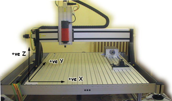
Movement: X 1000mm Y 1200mm Z 240mm Linear
Max material size is dependent on cutter dimension with the above axis travel limits.
** Your material height [including base board] must not exceed 120mm **
Rotary 4th axis capacity: 160mm dia. x 600mm length
Max feedrate: 4m/min
Roughing Cutter
20mm dia. flat bottomed
1500mm/min horizontal feed
500mm/min plunge feed
10,000 rpm spindle speed
5mm step depth
Finishing cutters - ball nose
3000mm/min horizontal feed
500mm/min plunge feed
16,000 rpm spindle speed
![]()
Distance X dictates the maximum depth of cut - approx 110mm
Distance Y has to accommodate the fixing plinth for the job, the thickness of the workpiece and the tool clearance height.
Tool Clearance
![]()
To get maximum depth of cut we can use long series cutters or an extension arbor as pictured above.
Which ever method we use, the 25mm dia. clamping nut will need to be considered for side wall clearance when using cutters less than 25mm dia.
Material Clamping
Consider clamping setup *here*
Minimum 10mm thick MDF for base board.
7mm dia. holes drilled at suitable centres in 50mm increments.
Make sure there is adequate cutter clearance around workpiece to baseboard securing screws.
* IMPORTANT * - make the wood screws you use to secure the workpiece onto the base board do not protrude into areas which will be machined - this will scrap the router cutter.
SK20 Collet