![]() Design & Tech CAD
Design & Tech CAD
Reference geometry
Variable Section Sweep
Layers & visibility
Adv. Rounds
Mathematical control
Advanced Patterns
Draft & Split plane Trim
Geometry from 2D graphics
Model analysis
Accuracy
Skeleton based surfacing:
Model Analysis
Section Curvature
Splines
Boundary Blend
Construction and manipulation
Trim, Merge & Solidify
3sided surfaces
Offset Surfaces
3 sided surfaces
You will regularly meet situations where the skeleton which forms the boundary of your proposed surfaces are comprised of 1, 2, 3, 5........ curves rather than the recommended 4.
You need to revisit [here] how a boundary blend surface is constructed before you can decide how to deal with these situations.
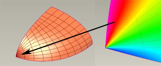
If you create a surface with 3 sides [as above] you will have 2 curves in one direction and one in the second direction. The pair of curves will converge at one end, at this point you are trying to blend over a distance of zero.
This convergence will cause ripples in the surfaces near the convergence. This is OK if the surface is not going to be thickened but may cause problems if you try and make the surface solid. There could be alot of modelling between creating the surface and later on thickening it only to then have to change the original surface and deal with the consequences.
Construction methods for 3 sided boundaries
Trim out the converging corner and replace with a 4 sided patch. Notice the shape of the trim to make the UV isolines in the new patch blend as naturally as possible.
Try not to be constrained by visualising surface in their end form. Can the surface be overbuilt and trimmed back.