![]() Design & Tech CAD
Design & Tech CAD
Arbortext IsoDraw - Technical Illustration
This software has two elements; CAD Process for converting 3D files into technical illustrations, and the IsoDraw core functionality for creating 2D line work.
Overview
-
Open 3D model
-
Orient model
-
[Maybe] Explode parts
-
Convert to 2D
-
[Maybe] Create connection lines, annotation etc.
-
Preview
-
Export to bitmap
Shortcut keys
| 1 | select tool |
| X, Y, Z | select csys vector for dragging, rotating etc. |
| R | Rotate Tool |
| ctrl K | on/off - preview - after converting to 2D |
Procedure
Ctrl O - open asm/part file - only native ProE part files in this version, not ProE assemblies. Export assemblies from ProE as STEP/IGES
Make sure Select Assemblies is unchecked
To show assembly structure for easier part selection:
Window > Show object window
For navigation around the sheet:
Window > Navigator
Change to Wireframe for better edge selection
Window > Projection > Isometric view - to establish initial view
To rotate
Use Select & Manipulation Tool [1] to select axis in csys or use the 3D Select Axis tool to select an edge
Use the Rotate Tool [r], shift and click in graphics area to activate angle control.
To move on sheet
As above select csys axis or edge to show movement vector
Use Select & Manipulation Tool [1], select the part and drag. Crtl A to select all parts
** Save as an .iso file before continuing to 2D ** - File > Revert to revert back to the 3D file for changes positioning, orientation, etc
Change to 2D - Convert to 2D illustration tool
Experiment with the Thin line threshold - Revert to try different levels
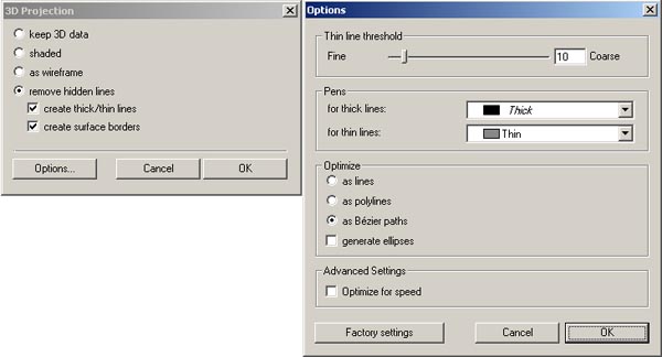
Ctrl K to Preview
If there are too many tangent surface patch edges - see image at the top of this page - you might want to delete some lines. First you need to ungroup the image:
Select the objects > Element > Ungroup
This may have to be applied a couple of times to progressively break down into the smallest elements, these are then pickable and can be deleted
To change a line thickness, select the line and then select the appropriate pen.
Dbl click pen to change line thickness
Line 'shadows'
Use the line tool to create dashed connecting lines between exploded parts
For when you've created a connection line which overlaps other entities - view in
preview mode - Ctrl K
Standard Parts Library including posed hands and tools:
Window > Show Library
When you've finished manipulating your image, File > export as a vector or pixel image.
Parts Library: http://www.technical-illustration.co.uk/swf/Library/ISO-Library.htm
3D import vid: http://www.technical-illustration.co.uk/swf/Import-3D/import_demo.htm
Images: http://www.khulsey.com/main_english.html
Tutorials: http://www.khulsey.com/student.html
Photoshop Tutorials: http://www.photoshopsupport.com/tutorials/kh/painting-techniques.html