![]() Design & Tech CAD
Design & Tech CAD
![]()
Help >
Manual for the full instructions
File format:
.bip – the model, scene and materials are saved in this
file
LMB, MMB,
RMB - left, middle or right mouse buttons
K - hotkeys
list
RMB Menus –
context sensitive – place the cursor over the part or background and
then RMB
These are the main steps in order:
Model Import
Keyshot in
the labs has the ProE plugin installed and will
therefore recognise native ProE parts and assemblies.
Assemblies will keep the part structure.
Pick Options or Dbl
Click on any of the parts to access the Options
window. In the Scene tab you can manage the parts
in the scene.
If your ProE model does not
import correctly there could be a number of reasons:
Does the assembly import with
the parts incorrectly oriented? Check your constraints in the
ProE assembly, if the parts are not fully constrained
or there are ambiguous constraints then KeyShot may
misinterpret their relative position.
Are construction surfaces showing in the model?
Make sure any unwanted surfaces are hidden on a layer.
If all else fails, which it
sometimes will in the world of 3D import/export, from
ProE, Save As a neutral model format
such as Step.
Merge with current scene - select
this option when you want to add multiple models into the same scene.
You may need to move the existing object first so the newly imported
object doesn’t overlap it - see below.
Model Orientation
If you’re lucky your model
will import in the correct orientation, if not…..
Options >
Scene tab > pick the part/asm name at the top of the
tree
Use the rotation increase/decrease arrows to
rotate the model and then the Snap to Ground option.
Shft +
Alt + LMB - move the model off the
centre on the ground plane
Camera Position
In rendering software,
visualise the camera position moving rather than the model moving – we
are viewing a scene.
Alt + LMB - Tumble
the camera around the focal point
Alt + MMB - Pan
the camera
Alt + RMB – Zoom
or ‘Dolly’ the camera
Applying Materials
Open the Materials library, simply drag and drop onto the model.
Dbl click
a part or RMB (over the part) > Edit Material
to edit the Material properties
Textures
These are pixel based
images which over ride the Material. Access through the Texture
tab in the Material properties.
Bump Maps
See CAD/CAM Pages >
Rendering > Bumpmaps
Bumpmaps give the
impression of a textures surface by adjusting the surface normals.
There are some bumpmaps in the Materials library under
the Texture tab.
Labels
You need to use a tiff with transparency layers to
create a see through ’label’, and move it on the model to see it when
you first apply.
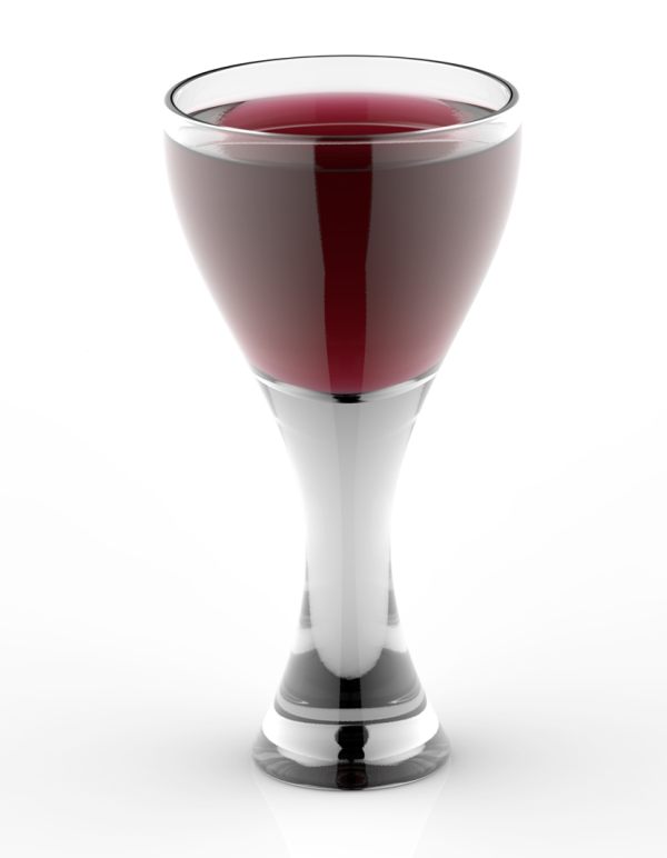
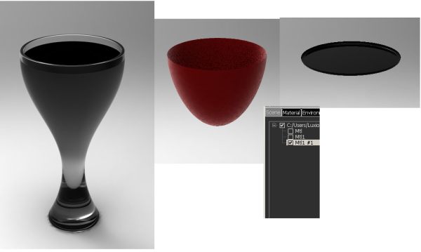
Liquid in
Glass Setup
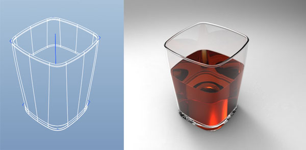
The image at the top this page took some input from some experts to get up and running as this was my initial result:
First suggestion was to put a tiny gap between the glass container model and the liquid model. This worked fine and produced this image:
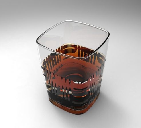
But the gap in the model above means there is no glass air interface - the light travels from liquid to air then from air to glass. The input back from this was that for maximum realism the model should be created not with a gap but with 3 surfaces;
-
the glass air interface - liquid top surface
-
the glass air interface
-
the glass liquid interface
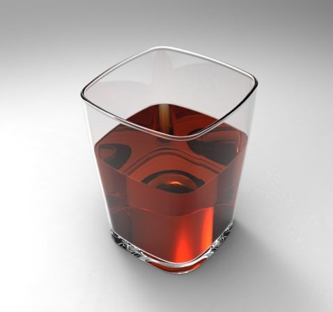
Download the file below HERE
This was from the KeyShot guys:
" That does look good,
but it is still a bit off due to the small gap you had to create. The
reason you need to set up this model like the wine glass is to be able
to pull the refraction of the liquid inside the glass to the very edge
of the outer glass surface. Being able to see the thickness of the glass
surface like this is incorrect.
This file is already set up
for proper "liquid-in-glass" rendering and it shows the important steps
beyond just having 3 surfaces to represent the varying "interfaces"
between liquid, air, and glass.
Splitting up the surfaces in
this way is important because you need to set different "IOR" and "IOR
out" settings for each of the surfaces.
The IOR is the index of
refraction for the "inside" of the surface, and IOR out is for the
"outside" of the surface.
So, looking at the wine glass bip file we do see
that there are three surfaces. The outer most surfaces covers most of
the glass itself and you'll find the material is a solid glass with an
IOR of 1.5. This means the inside of the surface will refract light like
glass since glass typically has an IOR of 1.5. The IOR out for this part
would be just 1, since the outside of the surface should refract like
air (no refraction) and air has an IOR of 1.
That's the easy surface, the
next surface, the top of the liquid is similar. You need to have the
inside of the surface represent the liquid and the outside should
represent air. So, for the wine glass the top of the liquid has an IOR
of 1.33 (the IOR of water) and an IOR out is 1 since it is, again, air.
The third surface, the
"interface" of the liquid meeting the glass is the tricky one. On the
inside of the surface you have the liquid, and the outside you have
glass. So, for the wine glass you will see that this surface has an IOR
of 1.33 since the liquid is on the inside, and an IOR out of 1.5 since
glass is on the outside.
You can get even more complicated by applying the
same technique to the color settings of the dielectric material to
create proper colored liquid and colored glass renderings.
Here is my rendering of the
wine glass that has these techniques applied, notice the accurate
refraction of liquid within the glass. Just like the real photo above.