Manual Positioning
Mechanisms
Animation
Mechanisms
Before you proceed with the mechanism extension you need to fully understand assemblies and Degrees of Freedom (DoF). Be careful with your reference selection - generally only choose references from two parts to make a connection.
The mechanism extension allows you to simulate and analyse a mechanism which has sliding and rotating joints. Once the assembly has been created it can be simply dragged on screen or motors can be attached to the joints which will simulate a controlled movement through an analysis.
Joints can be limited in their range of movement and a motors characteristics need to be carefully considered. An analysis can then show any interference between parts, trace a curve of the mechanism motion or create a movement envelope.
Some steps are carried out in the standard Assembly environment, some in the Mechanism extension - Assembly > Application > Mechanism |
The fundamentals steps are:
-
Assemble and connect/constrain base part as ground
-
Assemble moving parts with Connections, fixed parts with Constraints
-
Set connections limits where needed
-
Move into the Mechanism extension
-
Create Mechanism specific connections - gears etc.
-
Apply and setup Servo Motors to driven Connections
-
Set up Analysis
-
Run Analysis
-
If required - Replay Analysis checking for interference
Tips
-
If you want the base part to move out of the scene, connect it to the assembly csys using the weld connection this can then be disconnected
- Be careful how you connect
subassemblies ie. if you have an arm pivoting on a body and then
an entity constrained/connected to that arm - if that entity is
related to anything other than the arm it may not allow the arm to
move
- Always consider your Limit
Settings
- When defining/editing a Motion
Analysis consider how the initial configuration (through the
analysis or motor settings) of an entity is controlled this will
stop parts flipping to an inappropriate configuration when the
analysis starts
- Create a start position Snapshot
Common Connections and use:
Weld - aligns two coordinate systems - allows disconnection for animation
Slider one axis/edge sliding along another axis/edge with no rotation around the axis/edge.
Pin axis/edges aligned allowing rotation around the axis/edge but no translation along it.
Cylinder either - to allow rotation and translation on an axis rotational and slider motors can be attached to the connection or in combination with a separate but parallel pin connection to avoid conflicts.
Limits
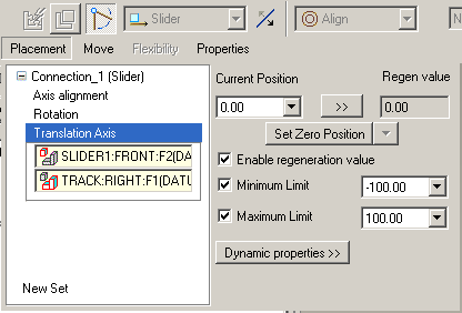
Most connections have the facility to limit the movement of a joint and set a zero and regeneration position. You will need to specify a zero reference on each of the parts to enable this function.

Servo Motor Profile
For constant motion in a single direction choose make the Specification velocity and the Magnitude constant.
For a reciprocating motion make the Specification position and the Magnitude cosine. Consider the Graph to determine the effect of variables A, B, C and T. Use the Initial Position preview to determine where your zero point is.
A = amplitude the distance the motor will reciprocate through
T = period time through a full cycle
B = phase degrees - offsets the cycle along the time line
C = offset mm - offsets the cycle along the amplitude line
