Views
Detailing
GA's and BOM
BOM -
Sub Asm
Explode States
Spline curves
Printing
3D Data Standards
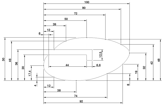
Dimensioning Spline Curves
In its simplest terms a spline is a smooth curve with a constantly changing radius which passes through a set of control points.
For further discussion look at this article [very accessible] or search on NURBS [Non-Uniform Rational B-Spline] or B-Spline.
Because it has a constantly changing radius we cannot apply a complete dimensioning scheme in our engineering drawing.
The first thing we need to define when considering how we might detail the spline is what is its purpose in the design? If its a purely aesthetic feature which has no bearing or interface with any other features then its details can be quite vague.
But if it interfaces with other elements then its definition must be more closely described. In this case, in modern industrial situations, the electronic data will be referred to for any manufacturing or modelling activities and a simple description would suffice in the drawing.
Remember that the the form of existing company logos are often very strictly controlled and you would then only give its position and extents and a reference to the original artwork.
But situations will still arise where more precise detailing is required - the artefact is being manufactured by manual methods, access to the original electronic data is restricted or cannot be used by the manufacturer.
Datum point display style
To show a point of reference for the spline dimensions you will need to show the datum points in the drawing - you would usually have these switched off. To control the graphical display of the datum points:
Tools > Options > config.pro options
Option: display_point_tags Value: no
The above Option may have to be added to config.pro - in the Option box (btm right) start typing the name of the option and the system will auto complete the option, or use the Find facility. Add/Change the option to the list, save the config.pro, copy it to your U:/ space if you want to use it for another session.
File > Properties > Drawing Options >
bs8888.dtl options
Option: datum_point_shape Value: cross or dot
Option: datum_point_size Value: appropriate to
line weight and sheet size
Method

Dimensioning each point is OK but can very quickly become cluttered - at least make sure this is a detail view or a separate sheet.

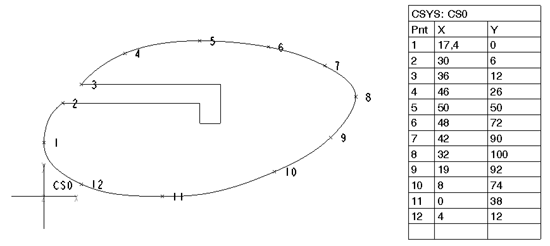
A tidier method could be to put the X Y coordinates into a table - make sure you define and dimension a point of reference.
To Save Spline Coordinates to a File
You can save spline points to a file with values in cartesian or polar coordinate systems.
1. Select the spline you want to modify.
2. Click Edit ▶ Modify.
The spline modification dashboard appears.
3. Click File. A dialog box
appears.
4. Associate
the spline to a local coordinate system.
5. Click the Save icon . The
Save A Copy dialog box opens.
6. Enter a file name.
7. Click OK.
Creo creates a spline point definition file
with the coordinate system type printed in the file. The spline point
definition file is a standard text file that you can edit using the
operating system editor.
