![]() Design & Tech CAD
Design & Tech CAD
Boundary Blend tweaks
ISDX - Freeform surface modelling
Scoops, bulges and
split surfaces
Analysis
Rhino
ISDX: Interactive Surface Design Extension
ISDX is PTC’s version of a freeform modeller which sits in Creo. Skeleton curves, surfaces and surface deformation features exist within a single Style feature. Although the Style feature has its own feature tree and parent child relationships are formed, the chronology of the features in the tree is not significant.
The interface can be viewed in single or four pane mode (below). Four pane mode (icon in top toolbar) is most useful when manipulating 3D curves which are tricky to visualise in from a single view point.
The ease with which you can setup curve attachments and end conditions, and the dynamic updating of all geometry as you interact with curves on screen makes this module very powerful. Unlike generic freeform modellers these relationships once set are fixed and will update as related geometry is developed.
Most functionality can be found under RMB menus. Select or hover over an entity to give appropriate RMB menus. Alt, Shift and Ctrl are useful modifier keys with most functionality.
Curves
![]()
-
Free – points placed arbitrarily in 3D space
-
Planar – points placed on the active plane/planar surface
-
COS – Curve on Surface – points stay within one surface patch indicated by the first pick
Use Shift when placing a curve point to ‘snap’ to an existing entity, also use shift to detach the point. RMB > pick soft point to toggle through underlying entities. You can snap to a datum plane but you may have to snap to its graphical boundary and then drag the point to the required position. It can take a bit of experimentation to choose the right reference which is appropriate for the required end/boundary conditions.
MMB to complete curve creation and create further curves, MMB again to return to select tool. MMB is generally a quick option to complete or repeat operations in ISDX
COS across patches – as a COS is restricted to a single patch you will have to think carefully about how you create a curve across multiple patches, particularly if you want end conditions to adjacent features. You could either; project a planar curve onto multiple patches, or; create separate COS curves and connect the end points across the patch boundaries.
Point Definition
-
Filled circle - Free Point
-
Empty circle – point attached to a curve/edge
-
Empty Square – point attached to surface
-
Cross – point attached to vertex or intersection point
-
Yellow line - tangent bar
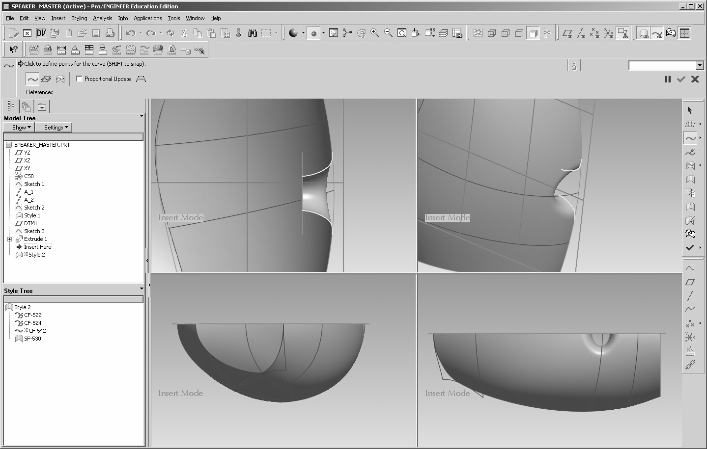
Point Attachment
In the above image, the curve in the right image needs to be G1 to the two adjacent edges. Two issues to watch out for; ·
Don’t attach to the vertex at the end of the edge (X point marker – left image below) – you cannot create a geometric (tangent in this case) relationship to a point. ·
Make sure you attach to the edge and not the underlying construction curve – you won’t form a loop for the surface. ·
Shift > attach to the edge > RMB > Pick Softpoint to ensure it is the edge and not the curve. ·
Edit > drag the point (should be an open circle) to the end of the edge to form a loop with the trimmed edges
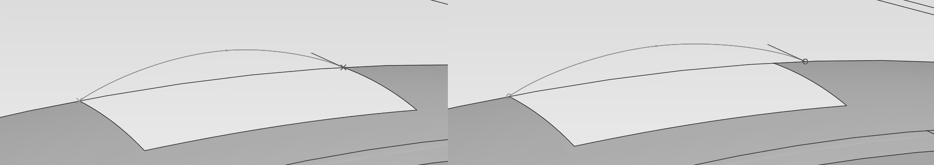
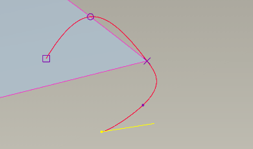
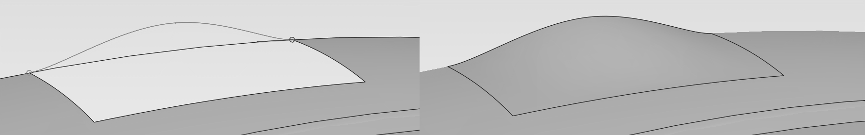
Curve Editing and End Conditions
![]()
Dbl click a
curve or use the Curve Edit icon to enter the edit
environment, simply drag the points to adjust the curve – all
connections will be maintained. Point > Point
Movement and used the nudge tool to move a point by controlled
increments. RMB menus to add or delete points.
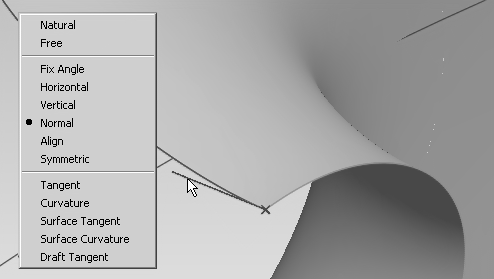
Setting up tangency conditions on curve ends and surfaces is fundamental
to success in ISDX. Select the end point of a curve to
display the tangent marker, hover over the marker and RMB
to select a tangency condition – remember it has to have an appropriate
relation to establish an end condition. Dragging the length of the end
marker changes the influences into the curve.
-
Hold shift whilst dragging a connected point to disconnect it and reconnect elsewhere
-
Also use alt and alt+ctrl to constrain movement
-
Trimming - COS cannot lie across patches - planar curve - project then trim
-
Shift+alt to extend curve - add new point from end
Surfaces
![]()
Follow the same principles for creating surfaces in ISDX as in the core ProE functionality – curve skeleton structure, blended 4 sided surfaces, 3 sided surfaces etc. Boundary selection is different:
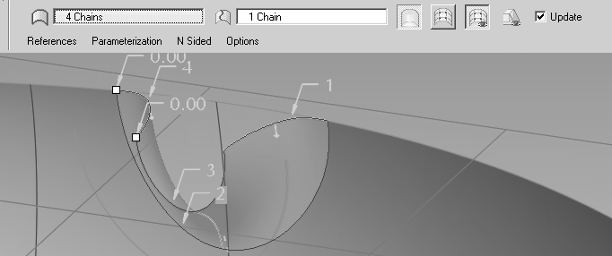
Boundary Blend Surface
-
ctrl pick the 3/4 boundaries (3 sided surface issues still apply) – selection order is irrelevant
-
if one boundary is a chain then ctrl pick the first element, switch to shift to pick the chain, return to ctrl to select further boundaries
-
internal curves are then collected after moving focus to the Internal Chains window
Blended Surface
-
Single primary curve in one direction, single or multiple curves in second direction
-
Select primary curve
-
RMB > Cross collector > select cross curve[s]
Lofted Surface
-
Ctrl pick multiple, unattached section curves in one direction
Surface Tangency
By default the system will establish boundary conditions according to the underlying curve conditions:
-
position – common boundary - G0
-
tangent/normal – G1
-
curvature continuous – G2
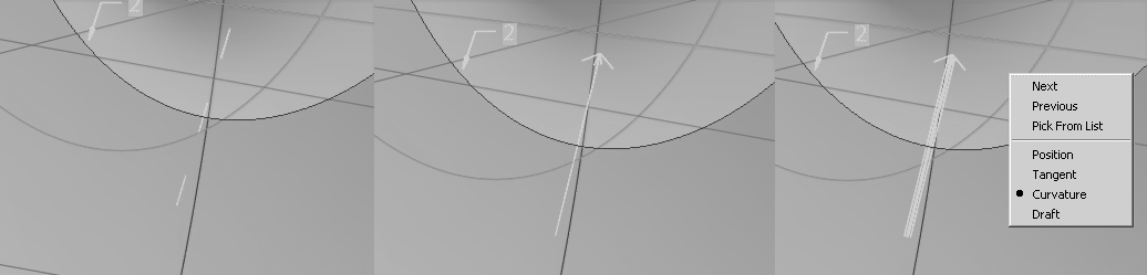
To edit the surface, double click the surface or RMB > edit definition in the ISDX model tree. Either RMB or pick the middle of the boundary marker to toggle between position (G0), tangent (G1) and curvature continuous (G2) connection – if the controlling curve conditions allow.
The arrow points from the leader to the follower surface, the follower surface changes shape to satisfy tangency conditions. RMB > Flip Leader on the arrow end allows you to (if relations allow) reverse the leader/follower order - this can have a significant effect on the form.
Surface Trim
Use of MMB makes the surface trim operation very quick and easy

-
start the trim tool
-
pick the surface to trim > MMB
-
pick the trimming reference – curve[s], surface, plane > MMB
-
pick the portion of the surface to delete > MMB
Direct surface edit
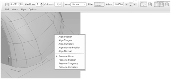
This tool can be used to edit surfaces for purposes of general modelling as well as make subtle tweaks to smooth out problem areas. The history of surface edits is maintained during future regeneration, so if the parent surface is modified, the surface edit is reapplied to the surface during regeneration.
-
Adjust the number of rows and columns for coarse or fine adjustment
-
Define how you want the points to move relative to the surface – normal to the surface, normal to a plane, free, etc.
-
Select individual points, Ctrl pick multiple points, select whole rows or columns.
-
Avoid distortion of surface edges - RMB menu on edge control lines and lock the edge.
-
Use the dashboard Nudge controls to incrementally move the control points
-
Experiment with the Filter to change the characteristics of the distortion away from the dragged point
Hiding ISDX Elements
You can RMB > Hide any ISDX feature whilst creating/editing the Style feature but this will not stay 'fixed' when you have exited the feature.
Layers - to hide ISDX surfaces - outside of the Style feature > Layers > RMB > new layer > change the Selection Filter (top right of graphics area) from Smart to Quilt > select ISDX surfaces to add to the layer > hide the layer
ISDX Style Trace Sketch Function - reverse engineering
Take some photos of an existing product or scan your sketches, you can then use the images as the basis of your initial reference curves. Don't put any geometry in this feature as you will have to suppress it to hide it.
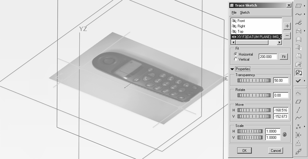
Whilst in a Style feature:
- Drop down menu Styling > Trace sketch
-
Select one of the existing planes or use the plus sign to add an additional plane
-
Search for you image file
Fit
Drag the two yellow bars to align to the the two reference points of a known distance - say the two axle centre on the image of a bike.
Input the actual distance and click fit
The bitmap will be scaled
Expand the Properties functions at the bottom of the Trace Sketch window to control your image
To set up 3 standard views, you may have to create a mirror image of your bitmap as it only applies to one side of the plane and there is no flip option.
Photo tips:
-
put a ruler in the image for easy scaling
-
use maximum zoom to avoid wide angle distortion - more zoom more isometric
-
leave plenty of space around the subject and crop the image - there is more distortion at the edges of the image and you don't need a high res image