![]() Design & Tech CAD
Design & Tech CAD
Boundary Blend tweaks
ISDX - Freeform surface modelling
Scoops, bulges and
split surfaces
Analysis
Rhino
Scoops, Bulges and Split Surfaces
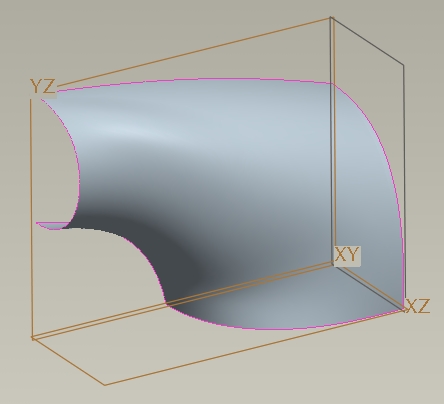
Split or tearing surfaces are large scoops or bulges that merge with the main surface on two or three of its sides in a fluid manner, indicating that they are parts of the main surface. The remaining boundaries, are created above or below the main surface giving the impression they are split or torn from the main surface. Such surfaces are often used to define aesthetic features.
A typical split surface is shown in the following figures
The challenge in creating these features is the construction of the tangent/curvature boundary and its underlying construction curves. This requires a good understanding of the 3D form, a clear statement of your design intent and identification of the boundaries.
If you are working from a sketch make sure you draw all the surface boundaries and show their conditions. If you are reverse engineering a product, draw the boundaries directly onto the product and again, indicate their condition.
Click on the image to enlarge
The above image shows a number of surface features which have tangency to the parent surface and could be interpreted as having issues of 3 sided surfaces and convergence. The right hand image shows the construction curves for these surfaces.
The tapering groove and the elliptical bulges are based on simple rectangular surfaces. All the curves and surface boundaries have tangency to the parent surface.
The top and bottom features are rectangular peel surfaces with fill strip surfaces. The top one has tangency on 3 edges and the bottom on one edge.
5 Sided Surfaces
One of the trickiest scenarios to overcome is when your form suggests a patch which does not obviously suggest how it can be broken into multiple 4 sided patches or overbuilt and trimmed.

 |
1. Initial curve set – simple sketched datum curves - ensure you have curve end normalcy where needed
|
|
2. Construction curve to enable initial 4 sided – curve thru’ points or ISDX free curve - again, consider end conditions
|
|
|
3. First 4 sided – boundary blend or ISDX |
|
|
4. Trimming curve – ISDX COS, projected curve or simply extruded surface cut. Make sure the curve is sympathetic to its opposite blend curve. |
|
|
5. Trim initial surface
|
|
|
6. Second 4 sided surface – some tweaking of the trim curve is likely to be needed. If you can’t create appropriate boundary conditions you will have to revisit your construction curve end relationships and end conditions
|
|