![]() Design & Tech CAD
Design & Tech CAD
Fundamentals
Sub Assemblies
Patterns
Explode states & X sections
Bottom Up or Top Down Design
Building associativity through assemblies
Modelling in assembly mode
Model Analysis
Top Down Design and Data Sharing
Bottom Up or Top Down Design Methodology?
Most projects will involve individual part files brought together in an assembly. In our introduction to assemblies we looked at bringing existing part files into an assembly environment. Any interfaces between parts (e.g. hole centres, mating edges) were considered individually at the part level. If any changes were made in one part it is only through a good awareness of the implications of those changes that we ensured the parts still fitted together in the assembly.
This is referred to as a Bottom Up approach to designing. In reality we see a product as a whole, an assembly of parts, from the ’top’ down. Two key methods to move to a Top Down design approach are;
-
creating and modifying your models in the assembly environment and directly referencing geometry from other parts or the assembly
-
importing geometry or whole models from a 'master' model to a part file maintaining associativity to the parent part
Part Activate
Right click part name in Model Tree > Activate
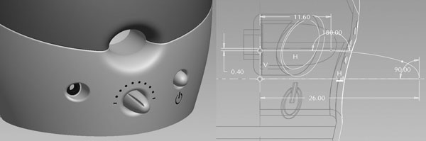
You are now in part mode but with the assembly still visible and available to reference as you create features and modify your model. In the speaker example below, the dimensions and position of the power and volume knobs are controlled by the speaker body.
The part files were created in the assembly and assembled with the Default constraint, the features are then created relative to the axis and faces in the speaker body. Therefore if the speaker body changes, the knobs change and clearances etc. are maintained. The knob diameter is controlled by a clearance dimension from the speaker body which is a sketch reference in the revolve, along with the axis and the end face.
Proceed with caution – as soon as you create reference across models you need to think very carefully about modifying or delete associated files – references can start falling over and solving issues can become problematic.
Skeleton Models
If we look at the relationships and interfaces between the different elements of our product, the Design Intent, and construct those at the assembly level as a basis for our part design then the parts will always follow this assembly framework or skeleton. This framework could simply be as simple as a few reference points and a couple of sketches created in the assembly file. The skeleton model can be a formal Creo Skeleton Model or simply an ordinary part file assigned as the skeleton model.
Creo Skeleton Model
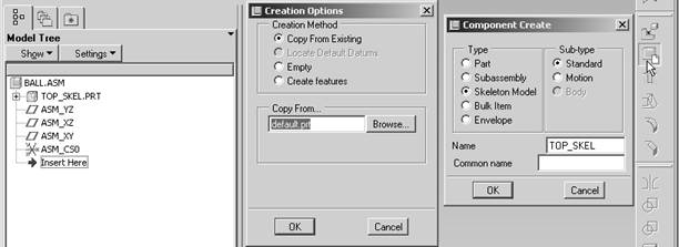
A formal Creo Skeleton Model is created via the Create a component icon in the assembly file and is insert at the top of the model tree. It has a couple of immediate advantages:
-
they do not show up in the BOM
-
they do not contribute to mass properties
Therefore they can be a ‘transparent’ framework part on which to construct your geometry.
Modelling in Assembly Mode
Working on your Part files (or Skeleton models) from within the assembly allows you to work on parts ‘in context’. You can directly reference to other parts and the Skeleton model and you can generally visualise the whole product.
Use the Create a Component icon on the right toolbar to create new part files as your product develops. If your part is to be built on references from other existing parts then simply assemble it using the default constraint placement, its position in the assembly is now controlled by the existing parts as it would be in reality.
Right click on the model name in the Model Tree and choose Activate. The interface is now in standard part mode but all the other assembly parts are shown. Right click and Activate the assembly name at the top of the Model Tree to return to assembly mode.
Parent Child Relationships and Circular References
Consider very carefully any references you create across parts in assembly mode. If you activate a part earlier in the model tree, all the later parts remain in the assembly. Make sure you do create unsound or circular references to child parts.
External References
Another very powerful method utilised in a Top Down approach is to reference external geometry to the current model. By bringing an image of specific geometry from one model into another we can build features (and maintain an associative relationship) based on that parent model. This does not have to be undertaken in the assembly.
Two significant features to be considered are Copy Geometry and Merge Part.
External Geometry Example
If you consider the example assembly below which is the handle and grip section of a power drill casing.

-
create drill_grip.asm
-
created New Component drill_grip_skel.prt as a skeleton model
-
created New Component case.prt
-
created New Component grip.prt
-
activate drill_grip_skel.prt, create reference surface and curves
-
activate case.prt, import surface and curves from drill_grip_skel.prt as Copy Geom feature
-
thicken surface, create offset pocket for grip, fillet edge
-
activate grip.prt, import surface and curves from drill_grip_skel.prt as Copy Geom feature
-
create offset curve for grip clearance, trim surface
-
thicken grip, fillet
If I want to change the form of the handle I make changes in the skeleton model, these changes will then migrate through any associated models, in this example, the case and grip parts. The ‘master ‘ model does not have to be a formal Creo skeleton model, any part file could be the source for the driving geometry.
Copy Geometry Method
-
Open the part file independent of the assembly
-
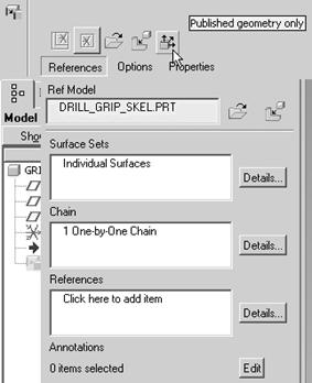
Insert > Shared Data > Copy Geometry
-
Deactivate the Published Geometry Only button
-
Click on References
-
Use the File Open icon to find your reference model
-
Decide how you are going to align the reference model in the current model through the placement window – generally use the Default constraint
-
Click in the Surface Sets, Chain or References window dependent on what geometry you want to copy from the external model.
If the reference model is already open then through the Window drop down menu go to that model window, otherwise a window will open showing the external model. Resize and move the window out of the way and leave it open until you complete the process. Select the geometry you want to copy.
Merge Part
Insert > Shared Data > Merge/Inheritance > find the reference part and assemble appropriately
This process allows you to import an image of a whole part into the current part file and maintain associativity.