Fundamentals
Sub Assemblies
Patterns
Explode states & X sections
Bottom Up or Top Down Design
Building associativity through assemblies
Modelling in assembly mode
Model Analysis
Assemblies
Key terms:
Constraints
Degrees of Freedom (DoF)
Base part
Align
Mate
Insert
Coincident
Offset
Oriented
File Management
Good file management becomes absolutely in the success of your assemblies. As you create new files your are creating relationships between those files - associativity - it is important you keep track of where those files are going.
Golden Rule: Keep .asm files and all associated .prt (or sub assembly files) local to each other - in the same folder
The simplest working folder would be on your U:/ space, but currently IT Services are not able to accommodate this so you will need to work from the hard drive if you are creating new files and need to maintain associativity.
-
Have all your files in a project folder
-
Put that folder in the Working Directory - follow the shortcut on TeachDoc for LDS003 or LDS011
-
Through the Model Browser tab in the Model Tree, RMB and set that folder as your Working Directory
-
All assembled part files MUST stay in the same folder as the .asm file
-
DO NOT change the name of any of the part files once they are in an assembly
To begin with, we shall bring different parts [or copies of the same part] into an assembly file and position them relative to each other with constraints such that they have no degrees of freedom [DoF] that is they cannot not move in X, Y or Z or rotate around the X, Y or Z axis.
See the Simulation section for creating assemblies with DoF which enable mechanism simulation and analysis.
+ve and -ve
All datum planes and surfaces have a +ve and -ve side. The positive side of a datum plane is brown, the negative is black. The positive side of a solid surface is the outside - the side you can see.
The positive direction is therefore normal to the surface away from the positive side.
Tip: When you first bring a part into the assembly, press the Ctrl and Alt buttons together and use MMB or RMB to move that part to the approximate position and orientation relative to the parent part.
Keep it simple and logical
Think about how the components might be assembled in reality, which references would be aligned - screw holes? edges? cylindrical axis? If you run out of fundamental geometry then use Datum Planes
A rule of thumb is; you need at least three constraints to place a part. There are exceptions to this rule - eg. aligning two axis which are perpendicular to each other will constrain a part.
Think about your references
To begin with, generally try and constraint a part to only one other part this will make modification of the assembly a lot simpler. If you are putting a wheel in a pair of bicycle forks, the wheel should only be related to the forks, not to the frame or the planes in the assembly environment.
To test how robust your assembly is try moving the base part and see if everything follows it or if the assembly fails.
Any squares next to the component name in your model tree mean a part is not fully constrained. A small square over a large square shows that that part is constrained but its parent isn't - therefore it still has DoF via its parent. If you can move or rotate a part using ctrl/alt middle/right mouse then it is not fully constrained. A component which is not fully constrained is referred to as 'packaged'.

All surfaces and planes have a positive and negative side. Any cylindrical surface (hole, protrusion, etc.) usually has an axis.
The process
![]()
Choose the Add Component icon (above) > select (Dbl click) the component to add to the assembly
Default Constraint
Be logical about which part of your product to assembly first - if you were assembling a car you would probably start with the chassis and not the steering wheel. This is the base part.
Firstly, make sure the base part is fully constrained. The base part can be simply placed by using the default placement icon this will align the default planes [xz, yz, xy] in the part to the default planes in the assembly environment.
Bring in the Component > RMB in the grahics area > Default Constraint
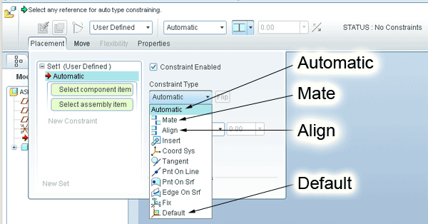
Primary constraints - Constraint Type
This is the first element of the constraint description.
Once the base part is assembled you need to think carefully how the subsequent parts relate to it.

Automatic Mode
By default, without entering the Placement window (above), the system in in Automatic constraint mode - simply select two appropriate reference and a constarint will be created according to the nature of the references - planar or cylindrical surfaces, axis, etc.
Continue selecting references and new contraints will be automatically created.
Align positive/negative side of the aligned surfaces or planes facing in the same direction. Two axis coincident - in the same place.
Mate positive/negative side of the aligned surfaces or planes facing each other.
Insert cylindrical surfaces concentric the same as aligning two axis but sometimes there is no axis.

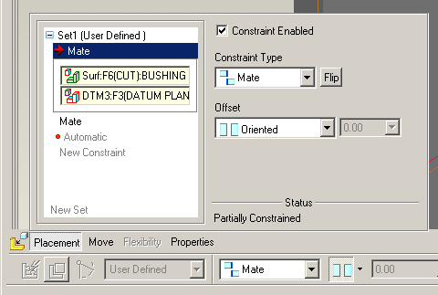
Secondary constraint - Offset
The offset element of the constraint controls how far apart the reference surfaces or planes are.

Coincident touching each other
Offset at a specified distance from each other
Oriented satisfying the primary constraint (mate, align) but floating. Their distance apart is dictated by another constraint, maybe the alignment of an axis.
Angular offset
If you want two parts at an angle to each other;
Align the appropriate axis
Constraint the position along the axis
This leaves one degree of freedom - rotation around the axis
Use crtl+alt and MMB and rotate the parts to approximately the correct angle
Within a new constraint, select the two surfaces/planes which set the angle [need to be parallel to the axis]
An angular offset constraint will be generated.
DO NOT USE THE FIX CONSTRAINT this will simply hold the part in its current position in the 3D environment but will not create any relationships between it and the other parts. This constraint is used for temporary placement of a part.
Using this constraint WILL lose you marks in your assignments.
Constraint Conflict
Take care not to have two constraints controlling the same alignment.
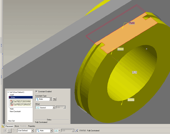
In the above example, the cylinder axis is aligned with the hole axis. The rotational angular position of the part is set by the alignment of the the flat at the top of the cylinder with the flat in the top of the hole. If the the surfaces were set coincident then there would two constraint trying to position the vertical height of the part - one would be pulling against the other.
This might be OK as long as the dimension are compatible, but if one of the dimension changes then the coincident constraint cannot be satisfied and the assembly will fail. The constraint for the parallel alignment needs to be simply oriented - parallel but floating.

