Reference geometry
Variable Section Sweep
Layers & visibility
Adv. Rounds
Mathematical control
Advanced Patterns
Draft & Split plane Trim
Geometry from 2D graphics
Model analysis
Accuracy
Skeleton based surfacing:
Model Analysis
Section Curvature
Splines
Boundary Blend
Construction and manipulation
Trim, Merge & Solidify
3sided surfaces
Offset Surfaces
Relations - Mathematically Controlling the Model
Creo Help > Fundamentals > Relations and Parameters or PTC_U > Advanced Modelling > Relations and Parameters
ProE models are driven by parameters, all model parameters have an identity;
Right click > Edit a feature in the model tree
This will show all the feature parameters in the graphics area
Info > Switch Dimensions will show you the parameters identities
Select a parameter in the graphics area > RMB > Properties > Dimension Text > Name allows you to change the name of the parameters giving the parameter a more logical name to use in relations.
These identities can be used in a mathematical equation to control the model. This can control can be at the Sketch, Part or Assembly level. This is a powerful tool for robustly capturing Design Intent and controlling the models behaviour.
Depending on your maths skills, you can take this control as far as you want using traditional operators and functions in equality or comparison controls, ie. d34=d6*7, d5 = d2*(SQRT(d7/3.0+d4)) or IF d1 > d2, length = 14.5, ELSE , length = 7.0, ENDIF
User Defined Parameters
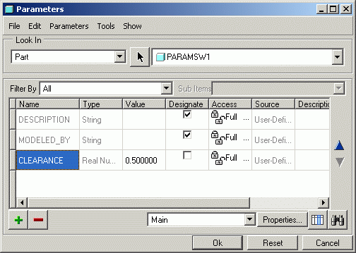
You can also create a list of unique parameters to use in relations which might defines say a general shell thickness, common hole size or clearance value. The CLEARANCE parameter below could be used to set all clearances on an injection moulded assembly, the one parameter simply has to be changed to change the whole assembly.

Creating Relations
In the Sketch, Part Or Assembly: Tools > Relations to enter the Relations dialogue box
If your in sketcher, the parameters will change to IDs
If your in part or assembly mode, pick the features [model tree or screen] to show their IDs
Pick those IDs on screen [or simply type them] to include in the equation
Driving Dimensions with Parameters
Create Relations as above use the Parameter name in the relation statement, eg. D6=clearance1 The Parameters can viewed and changed at the bottom of the Relations window. The model will have to be regenerated (CtrlG) to effect any changes.
Trajpar in VSS
Trajpar is a unique parameter which is used in the Variable Section Sweep function and is related to the Origin Trajectory length. This parameter varies from 0 to 1 as the sweep develops along the the trajectory.
O at the beginning of the trajectory, 1 at the end of the trajectory, therefore 0.5 half way along etc.
This parameter can therefore be used to control the sweep section within a relation.
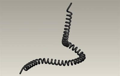
Example: 'Traditional' telephone cable

You cannot produce this form with a helical sweep as it would need to be a linear trajectory, so this method uses a VSS and Trajpar
Create a curve which represents the path of the cable - Curve thru' points, intersect curve or Style curve
Start a VSS and choose this curve as the trajectory - leave as Surface not Solid. Enter sketcher.

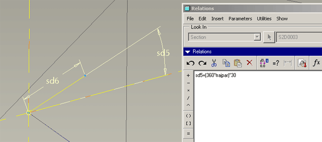
Construct a simple short line (sd6 above) attached to the end of the trajectory as above. Notice the dimensioning scheme - line length and angle
The angle [sd5] will be controlled by the relation: [angle] = (360*trajpar)*30 - ignore the *30 for the moment.
- Trajpar = 0 at the traj start
- Trajpar = 1 at the traj end
- at the traj start the angle = 0 deg.
- half way along, trajpar = 0.5, angle = 180 deg.
- at the traj end the angle = 360 deg.
The *30 means this happens 30 times over the length of the trajectory - 30 coils. Change the 30 for more or less coils.

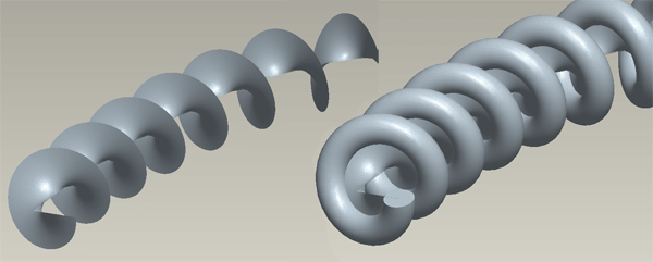
The outer edge of the spiralling surface is then simply used as the trajectory for a constant section sweep.
