Reference geometry
Variable Section Sweep
Layers & visibility
Adv. Rounds
Mathematical control
Advanced Patterns
Draft & Split plane Trim
Geometry from 2D graphics
Model analysis
Accuracy
Skeleton based surfacing:
Model Analysis
Section Curvature
Splines
Boundary Blend
Construction and manipulation
Trim, Merge & Solidify
3sided surfaces
Offset Surfaces
Variable Section Sweep
A standard swept feature [created under the same function] has a single trajectory and a constant [unchanging] cross section. The Variable Section Sweep (VSS) has an initial cross section which is referenced to multiple trajectories which influence [distort] the section as it travels along those trajectories.
Therefore, you cannot use an existing sketch or edges for the VSS section as it would then be referenced to that section and not be able to ‘distort’. As you cannot reference to a start or end section this would not generally be used as a fill between existing end sections.
Key points:
- Trajectories must be tangent chains
- Dimensions of the section vary but not the fundamental geometric elements
- A high level of control is maintained over the length of the resultant form
- The dimensioning scheme must be carefully considered – which dimensions are fixed and which are allowed to vary
- Reference to existing geometry with care
- Sketchplane placement is greatly effected by chosen trajectories and which is the origin
- There is a need to experiment with the combination of setting in terms of origin selection and section alignment
Because it is a more complex feature a thorough initial analysis of the planned form and the trajectories and section is needed. Then an understanding of how the feature is developed using this structure - this feature generally needs some fine tuning before it is successful.
Sketchplane
The sketch plane has to intersect all trajectories. The resultant solid cannot extent beyond the selected trajectories and therefore the trajectories need to be carefully considered in terms of the section orientation control.
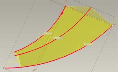 |
Section normal to origin trajectory - top curve |
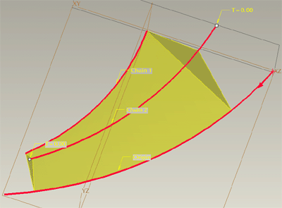 |
Section normal to origin trajectory - bottom curve |
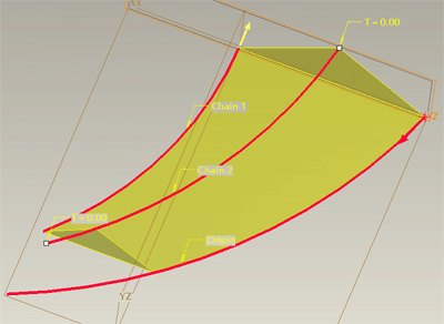 |
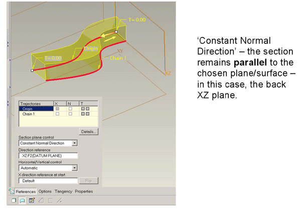
Section parallel to end plane - 'constant normal direction' |
Section behaviour
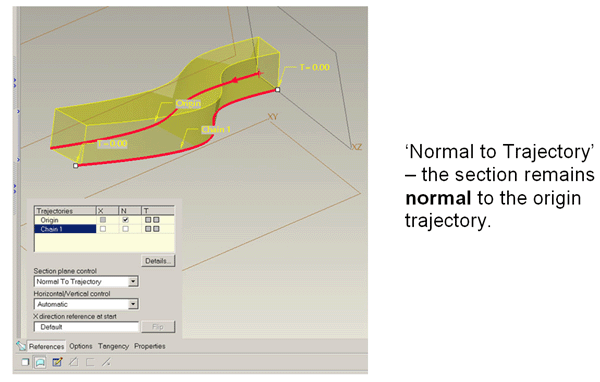
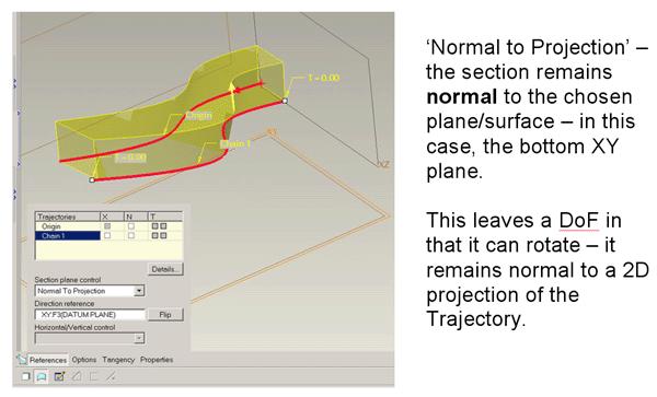
One the key concepts to understand with the VSS is how you influence the orientation of the section as it progresses along the trajectories. Experimenting with the order in which you select the trajectories and which section control option your choose is the key to success with this feature
The first trajectory you choose is the origin trajectory and by default the section remains normal [Normal to Trajectory] to this curve as the feature develops.
Related subject: Trajpar - go to the Relations section
