Introduction to 3D CAD modelling
Design Intent
Sketching
Intro to Creo through
the Extrude feature
Editing
the Model
Managing the Model
Robust Modelling
Revolve
Blend
Sweep
Swept Blend
Engineering Features
Edit Features
Reference Geometry
Helical Sweep
Edit Feature: all in right toolbar
Key terms:
Mirror
Pattern
Copy
Paste
Dependency
Dependency
Often, when you create a copy of an entity there will be an option to make the copy dependent or independent of the original. Any changes in the original entity will or will not be reflected in the copied instances.
![]() Mirror
Mirror
To create a mirrored copy of a single feature, number of features or group simply make your selection in the model tree, select the mirror tool and then select the plane about which the features are to be mirrored.
Model Symmetry
You can also mirror the entire model tree by selecting the model name at the top of the model tree and then selecting the mirror function. This more robust than mirroring a selection of features as it mirrors all the elements needed to create the mirror geometry.
Dependent
![]() or Independent
or Independent
![]()
![]() Pattern
Pattern

To create multiple instances [copies] of a feature or features in a regular pattern [or to fill a prescribed area] you can select the items and then use the pattern tool [or right click > pattern].
Patterns can be linear - line or grid, radial - referenced to an axis, or follow a curve.
All patterns need references to define their direction and characteristics.

The dashboard controls firstly define the type of pattern, this will then dictate which direction reference boxes are displayed. The number of copies in each direction is also displayed.
Remember to use your
right click menus as well
Simple patterns - Direction, Axis, Fill, Curve
These pattern types are the simplest to set up but do not give any control over the geometry in the individual copies.
Direction - choose a plane/surface to signify a direction
Axis - choose an axis to signify the centre of rotation
Fill - choose a sketch as a boundary to fill
Curve - choose a
sketch to follow
Axis pattern, equal spacing

Patterns with geometry control - Dimension pattern
A Dimension
pattern will allow you to control the geometry and position for
individual copies. This patterns form is dictated by the direction
references you choose - linear, radial or curve.
Driving dimensions
As with any other features, a pattern requires references. The important concept to understand with patterns is that you choose parameters [dimensions] which place the original feature to describe the direction or nature of the pattern.
The chosen dimension also indicates the positive direction. If you want the pattern to increment in the opposite direction you need to input a negative figure.
For a linear pattern
[as above] dimensions in X and Y
which place the original feature are selected to indicate the two
pattern directions. These references are placed in the two
Dimension boxes - Direction 1 and
Direction 2.
Radial pattern
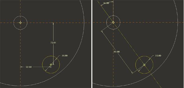
The driving dimension for a radial pattern [below] is the angular dimension placing the original feature.

The dimensioning scheme for a radial Dimension pattern must be carefully considered. The default linear placement of the sketch in the below left image will conflict with the radial pattern. The modified dimensioning scheme will produce a successful pattern.

Incrementally changing instances
You can also change the parameters of a feature as it is copied – eg. each instance decrease progressively in height through the pattern.
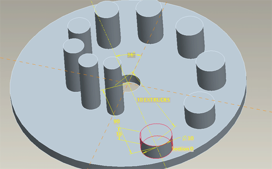
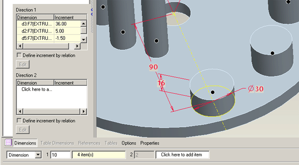
In the above example an extrusion has been patterned around the axis of the base cylinder. This pattern has then been altered so that as each instance of the original extrusion is created, the height dimension, the diameter dimension and the distance from the axis dimension are adjusted.
The parameter you wish to change is included in the appropriate direction box and the incremental adjustment input. In the above example the height dimension, diameter and the distance from the axis dimensions are collected in the Direction 1 box after the initial angular driving dimension.

Copying features
You can use the Copy, Paste, and Paste Special commands to duplicate and place features, geometry, curves, and edge chains. Using this functionality, you can copy and paste features within the same model or between two different models.
By preselecting edges you can create a copy as a datum curve either as an exact copy or an approximate copy – this will approximate a chain of tangent curves as a single continuous curvature spline curve.
Two methods for Pasting solid features:
- When you use Edit > Paste, the system opens the feature creation tool, so you can redefine the copied feature.
- When you use Edit > Paste Special, the system allows you to replace the original references with the new ones.
