![]() Design & Tech CAD
Design & Tech CAD
Introduction to 3D CAD modelling
Design Intent
Sketching
Intro to Creo through
the Extrude feature
Editing
the Model
Managing the Model
Robust Modelling
Revolve
Blend
Sweep
Swept Blend
Engineering Features
Edit Features
Reference Geometry
Helical Sweep
Introduction to ProEngineer through the
Extrude
feature
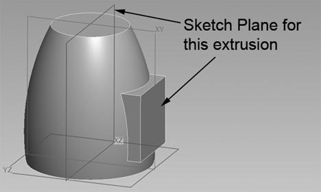
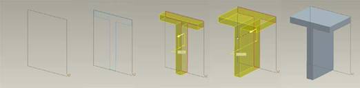
![]() Extrude: A 2D sketch is developed along a linear path to a specified
distance to create a 3D form
Extrude: A 2D sketch is developed along a linear path to a specified
distance to create a 3D form
The Extrude feature is the most common and simplest of the fundamental feature creation tools in CAD, it is a common start point in the building blocks which make up your model.
Base features -
Extrude, Revolve, Sweep, Blend - can either create or
remove material - See Video
HERE
Watch a video on how the use the Extrusion functionality HERE
Graphics area
Most of the control over the feature can be accessed through the graphics area right click menus, control handles and clicking on arrows.
Remember you have to press and hold the right mouse button to access the right click menus.
- right click menu to create
internal sketch
- right click on control handle [white square] to access options
- left click on arrows to change direction
- drag control handles
Dashboard
Most features are controlled through the Dashboard at the bottom of the graphics area. This has icons and popup windows which control the fundamentals of the feature.
Input boxes highlighted in yellow have focus so be careful you put information or references in the right box.
Solid or Surface
This feature should default to Solid. If the surface icon is highlighted then check your driving sketch is closed and valid for an extrude
Protrude or Cut
Do you want the created volume to add (Protrude) or subtract (cut) material from the existing model?
Thin feature
If you are producing a feature which mimics a sheet metal or tubular part then rather than spend ages in sketcher producing the offset line for the wall thickness, simply use the Thin option and specify a wall thickness. Your sketch can then be open or closed.
Depth Control
Use the right click menu via the depth drag handle or the dash board control to change the depth control. Choosing an appropriate depth control which robustly captures the design intent
![]() Blind – specified
distance
Blind – specified
distance
![]() Symmetrical – specified distance,
half each side of the sketch plane
Symmetrical – specified distance,
half each side of the sketch plane
The end surface of the two previous options is parallel to the sketch plane
![]() To
Next – continues until next
geometry
To
Next – continues until next
geometry
![]() Through Until
– can pass through other geometry to
selected reference
Through Until
– can pass through other geometry to
selected reference
The end surface of the previous two options is trimmed by the selected reference – if it’s a curved surface then the end face will be curved to match
![]() To Selected – as Blind
but distance defined by selected reference
To Selected – as Blind
but distance defined by selected reference
The end surface with To Selected will be parallel or trimmed dependent on selected reference
![]() Through All – intersects all
features in the model – as the model grows the depths grows
Through All – intersects all
features in the model – as the model grows the depths grows
Develop independently from both sides of the sketch plane
The Dashboard > Options drop down menu also allows you to develop the feature from both sides of the sketch plane with different depth control options.
Intersecting solid features will simply merge into each other as a single volume, so, if its more convenient, you can use a datum plane within a solid or extrude through and out the other side of a solid.