![]() Design & Tech CAD
Design & Tech CAD
Introduction to 3D CAD modelling
Design Intent
Sketching
Intro to Creo through
the Extrude feature
Editing
the Model
Managing the Model
Robust Modelling
Revolve
Blend
Sweep
Swept Blend
Engineering Features
Edit Features
Reference Geometry
Helical Sweep
Sketching
Key Terms:
Sketchplane
Sketch Orientation
Sketching References
Sketcher
Intent
Manager
Design Intent
| Curves - entities in a sketch whether they are straight or curved! |
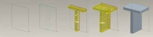
Sketch based features
A 2D sketch is developed to create a 3D form
Standalone or Internal Sketch?
The 2D driving sketches for your features can either be; Internal to [embedded within] the feature - created whilst creating the feature, or, standalone independent features. Some sketches have to be internal - the section sketch for a sweep for instance.
Internal
For simpler features such as extrude and revolve it is generally quicker and creates a tidier model tree to create the sketch within the feature. Internal sketches can also be checked using the Analysis Tools (see end of this page) relative to that feature type.
Start the feature > right click [in the graphics area] > Define Internal Sketch
Independent
Independent sketch features which are selected whilst creating the model feature have a number of advantages for more complex geometry and feature creation methods such as sweeps and blends;
You can visualise the form before creating the feature though the 'wireframe' sketches
If the feature fails or is deleted you do not lose the sketches driving the feature.
Setting up the Sketch
When creating most sketched based features there are three common setup consideration which can be summarised as:
1. Sketchplane
The
Sketchplane
is the flat plane – surface or datum plane –
on which you are going to draw the 2D driving sketch underlying your
feature. Whilst in Sketcher, click on the
![]() icon in the Sketch toolbar to change the sketchplane or orientation.
icon in the Sketch toolbar to change the sketchplane or orientation.
2. Sketch Orientation
The Sketch Orientation is generally assigned automatically and you can usually skip this step and accept the reference chosen by the system.
It decides in which of the four possible orientations the ‘four sided’ sketchplane is viewed - like decided whether you use a piece of paper in landscape or portrait. The sketchplane is parallel to the screen, there has to be a surface or datum plane which is perpendicular – at 90 degrees – to the sketchplane which can be chosen to face to the right, left, top or bottom.
Sometimes you may want to change the sketchplane orientation. The reason behind this process is to orientate the coordinate system within the sketch.
There is also a direction arrow which indicates which side of the Sketch Plane you are looking onto - click the arrow the flip the view direction.
Creating text on a part is an obvious example where the Sketch Plane orientation is very significant.
3. Sketching References
The position of your
sketch on the sketchplane needs to be described with dimensions and
geometric constraints - refer to the previous section on
Design Intent.
Sketching References
are the
entities from which dimensions will start. You will need to decide
on appropriate sketch reference before you start
sketching. Click the  sketch
references icon to add or change sketching references.
sketch
references icon to add or change sketching references.
A coordinate system, point or perpendicular axis can be chosen alone and will generate both vertical and horizontal dimensions. Otherwise choose a vertical and a horizontal perpendicular plane (surface or datum plane) – edges are not robust references.
Sketcher is the 2D sketching environment in which you will create feature driving sketches or planar reference curves.
The brown dashed lines
are the sketch references. The
Sketching References
dialogue box can be returned to add or delete references at any time
via the sketch references
icon
Constraints
Geometric Constraints
A Sketch is a set of curves which must be Resolved before it can be used to generate a solid. The Intent Manager constantly resolves the sketch as you add curves to it. To be resolved, a Sketch must contain enough dimensional and geometric constraints to fully describe the curves.
As your sketching and the Intent Manager is trying to apply/snap a particular constraint:
-
right click to toggle through lock/disable/enable the constraint
-
use Tab key to toggle active constraint
-
press and hold Shift to disable snapping to new constraints
See HERE for expanded explanation of Geometric Constraints
Tangency on Wikipedia - HERE
Dimensional Constraints
Once you have some curves, you've dragged them to the right proportions and you've added geometric relations then you can add dimensions - dimensional constraints.
LMB to select the geometry to dimension, MMB to place the dimension. Place the dimension with MMB in the position you would draw the dimension on paper.
-
LMB to pick a line, MMB to dimension the length of that line
-
LMB to pick 2 parallel lines, MMB to dimension the distance between the lines
-
LMB to pick 2 non parallel lines, MMB to dimension the angle between those lines
-
LMB to pick an arc, MMB to dimension the arc radius
-
LMB to pick a circle, LMB to pick the circle again, MMB to dimension the circle diameter
-
DO NOT dimension a circle with a radius
-
LMB to pick points or centres, MMB to dimension the distance between those points
Useful dimensions:
In sketcher, select a chain of lines, curves, etc to create a perimeter, Edit > Tools > Convert to > Perimeter and it'll create a dimension for the perimeter length.
Arc length: LMB - arc endpoint, arc endpoint, arc. MMB to place dimn. As below:
Perimeter - dimension reporting the combined length of a closed loop of curves
Ctrl Select the loop of curves > select an existing dimension on one of the curve to show the position of the perimeter dimension.
Good Sketching
-
Curves [to scale]
-
Geometric Constraints
-
Create Dimensions
-
Modify Dimensions
Creating a robust and successful sketch as the basis of most of the common ProE features is a crucial step on the way to a successful model.
Step 1: Use
the sketcher grid and zoom in/out to make the graphics area the same
size as your intended sketch.
This will avoid problematic ‘bit by bit’ scaling through modification of
dimensions in the sketch once it is completed. Large movements of
entities will often result in extreme distortion of the sketch.
Step 2: Using Lines and Arcs
(rather than trimmed Circles and Squares) starting from one point and
create the sketch in a continuous line.
Trimming circles and squares can often result in end points becoming
disconnected so causing open loops which are hard to solve. You are
also more likely to create lines on top of lines - very hard to track
down. Starting from one point and switching from line to arc as you
work around the loop will ensure good connection.
Step 3: Create the sketch to
the correct proportions.
This will avoid lots of
resizing work. Drag points and entities to approximately reshape the
geometry.
Step 4: Apply geometric constraints.
Connect the sketch to the sketching references and use geometric
constraints before dimensional constraints to fix its shape and
proportions. This will minimise the number of dimensional constraints.
The common constraints you will use are Tangency and Coincidence.
Step 5: Apply dimensional
constraints.
It is good practise to try and leave the sketch with no grey, weak
dimensions. This ensures all dimensions have been considered and
checked.
Step 6: Modify the dimensions.
Using the pick icon,
simply double click a dimension to modify it. Also, using the pick icon
you can drag a box around all of your dimensions to select them and then
pick the modify icon to list all the dimensions for easy modification.
Uncheck the regenerate option as this may cause distortion as
each dimension will be updated as you make changes.
Step 7: Resolve sketch
failures.
If the sketch fails it is most commonly due to either disconnection
between points causing an open loop – look for weak dimensions of zero –
or because you have lines on top of lines – very hard to find. This
last issue is the main advantage to creating the sketched loop an entity
at a time continuing from the end point of the previous entity using
line and arc segments
This method of creating robust sketches is by no means the only way, there are always exceptions everyone develops their own techniques but I have found it to be a good starting point.
Round up/down your dimensions
- do you really want your
part 47.63mm wide or 42.97degs? Remember, these dimensions will
migrate to your engineering drawings.
Interrogating your sketch
For a solid feature your sketch needs to be either;
- a single closed
loop
- multiple closed loops which do not overlap
Common issues which cause a sketch to fail are;
Tags
Usually through bad trimming. Look for unexplained dimensions.
Line on line
One line exactly overlapping another is seen as another [incomplete] loop. Usually through bad trimming. Tricky to find. Look for unexplained dimensions.
Disconnected endpoint
Endpoints seem to join but don't have appropriate constraints. This can happen when using the copy edge function.
Section Analysis Tools
With both Internal and Independent sketches, the system can use a range of tools to highlight issues with your sketch.