Introduction to 3D CAD modelling
Design Intent
Sketching
Intro to Creo through
the Extrude feature
Editing
the Model
Managing the Model
Robust Modelling
Revolve
Blend
Sweep
Swept Blend
Engineering Features
Edit Features
Reference Geometry
Helical Sweep
Reference geometry
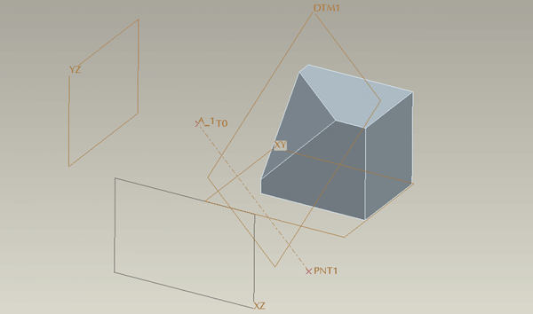
These features do not form part of the model but are created in order to establish a reference for model features where no suitable reference exists - remember, everything has to be ‘fixed’ in our 3D space.
Degrees of Freedom (DoF) – the freedom to move in a direction which has not been constrained – fixed to another entity. Can the entity be moved in any direction or rotated?
The reference geometry you create also has to referenced in space such that it has no DoF. You will not be allowed to complete the feature until all the DoF have been resolved – until it has been fully constrained. How many references or constraints are needed to place your new reference feature is dependent on what sort of geometry it is and what you are constraining it to.
To 'collect' references
Whenever you are presented with a references window you will need to hold the Ctrl key if you need to 'collect' multiple references - standard Windows functionality.

Normalcy - the term normal is generally used instead of perpendicular or orthogonal to describe a line or axis being at 90° [in all directions] to a plane or surface.
![]() Planes:
Planes:
parallel offset from another
plane/surface
normal to a plane/surface
through an axis/line/edge/point
angular offset from another plane [must be
combined with through axis/line/edge]
![]() Points:
Points:
DO NOT put datum point on curve ends or surface edge ends - these are vertexes and are already seen as points which can be connected to.
Constrained to other references:
On a surface/plane and referenced to other
entities, ie. two other surfaces
On an edge/line relative to the end of the
edge, line
On an axis relative to another reference
![]() Offset from a csys in x,y and z
Offset from a csys in x,y and z
![]() Sketched on a surface/plane
Sketched on a surface/plane
If you are creating multiple points then include them all in one feature
if possible – this can result in a significantly shorter and tidier
model tree.
![]() Axis:
Axis:
Through a point/vertex/curve/edge
Normal to a surface [doesn’t have to be
planar] or plane
Curves:
![]() Sketched
on a surface/plane
Sketched
on a surface/plane
![]() Thru Points - a
curve can be constructed to pass through any number of points -
reference points, vertex's, curve endpoints - in space
Thru Points - a
curve can be constructed to pass through any number of points -
reference points, vertex's, curve endpoints - in space
![]() Projected onto a
surface
Projected onto a
surface
