Introduction to 3D CAD modelling
Design Intent
Sketching
Intro to Creo through
the Extrude feature
Editing
the Model
Managing the Model
Robust Modelling
Revolve
Blend
Sweep
Swept Blend
Engineering Features
Edit Features
Reference Geometry
Helical Sweep
Helical Sweep
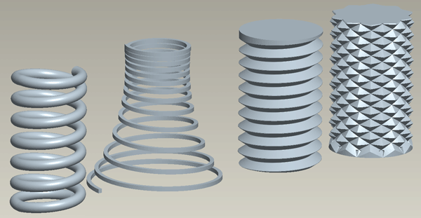
Springs and screw threads are the classic examples of using a Helical Sweep, but think about how you might produce a knurl pattern using this functionality. Think of this feature as a standard sweep along a helix.

Unfortunately this function is still under the 'Menu Manager' interface.
Insert > Helical Sweep > Protrusion or Cut
The feature properties window opens up and starts with the features attributes.......
Attributes
Constant or Variable pitch?
Definition: the distance travelled along the axis for each 360 degree revolution of the helix.
In this section we shall just deal with a constant pitch, go to the end of the section for guidance on setting up a variable pitch
Section Orientation?
This defines whether the section sketch plane remains vertical - parallel to or through the axis [default] - or if it is normal to the trajectory of the sweep.
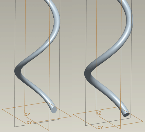
The effect of this choice can be best seen in a sweep with a 'fast' helix - a pitch greater than the profile length. In the image below you can see the sweep section is distorted if the option Through Axis is used [feature on left] - the sketch plane is at an acute angle to the trajectory.
The feature in the right of the image looks more like a standard sweep - the sketch plane is always Normal to the trajectory.

Right or Left Handed?
Simply the direction of the helix. A standard screw thread is right handed.
Done
Consider the sweep from the side view, we first need the sketch plane for the axis and outer profile.
Direction [view direction onto sketch plane] > Okay or Flip
Sketch plane orientation - pick direction, then pick a perpendicular plane to face in that direction.
Now you are ready to sketch the cross section of the form.
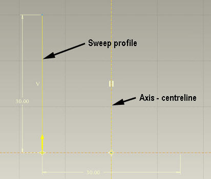
Swp Profile
Create a centreline as the sweep axis.

Create a line to show the outer profile of the sweep - this does not have to be vertical or even a straight line [draw this to the left of the axis to avoid confusion in the section sketch]
Complete the Sketch
Pitch
This is the distance the helical 'spiral' moves along the axis for each 360 degree turn. Input a figure in the prompt in the text area of the screen and hit the tick.
You will then enter a 2nd sketch environment to create the cross section of the sweep
Section
Make sure you identify which reference is the axis and which is the outer profile as its an easy mistake to draw the section up against the axis!
Complete the sketch
Variable pitch
Select Variable rather than Constant pitch [second feature in top image above]
The Profile can still be any shape.
A single line will allow a start and end pitch with a smooth transition from one to the other over the length of the sweep.
If you want the pitch to be different values at various points along the profile then you need to break the profile into sections at the points you want the pitch to vary.
You will be prompted for the start and end pitch.
A graph will then appear which shows the pitch along the profile. Pick the break point on the profile sketch to add them to the graph and define a pitch at that point.
If you want to change the values, use the Change Value option in the Pitch > Define Graph menu.
