Introduction to 3D CAD modelling
Design Intent
Sketching
Intro to Creo through
the Extrude feature
Editing
the Model
Managing the Model
Robust Modelling
Revolve
Blend
Sweep
Swept Blend
Engineering Features
Edit Features
Reference Geometry
Helical Sweep
Swept blend utilising reference geometry
The
![]() Swept Blend
creates a feature which is defined by two or more cross sections
positioned along a trajectory - the resulting form is influenced
by the sections and the trajectory.
Swept Blend
creates a feature which is defined by two or more cross sections
positioned along a trajectory - the resulting form is influenced
by the sections and the trajectory.
In the example below, the edge of the model is used as the trajectory and three different sections are placed along the trajectory.

In the above example the dimensions of the 'L' shaped lip change as it sweeps around the top edge of the base feature - these dimensions are controlled by the 3 sections positioned around the edge.
Common Considerations:
- As with a blend, each cross section must have the same number of vertices (points), or in other words, be made up of the same number of lines. This defines how one section is connected to another.
- Try and plan the feature so that the section are not swept around the inside of any curves in the trajectory - problems can occur if the section has to be ‘compressed’ inside a tight curve.
- The cross sections and the trajectory can be sketched or selected from existing edges or reference geometry.
Pick the Swept
Blend
![]() icon from the right toolbar. The system defaults
icon from the right toolbar. The system defaults
External Sketches
Creating your trajectory and sections as separate features is a more efficient strategy as you will not lose your construction geometry if the features is deleted
Trajectory
Select a sketch or solid edges to define the trajectory. If your trajectory is made up of multiple edge elements then you will have to create a 'chain' of edges. DO NOT use CRTL to pick multiple edges as this will select multiple trajectories.
To create a chain of edges:
-
Select the first edge
-
Press and hold SHIFT
-
Pick the first selected edge again - this changes the selection method to chain
-
Still holding SHIFT, select the other edges which make up the chain
Sections
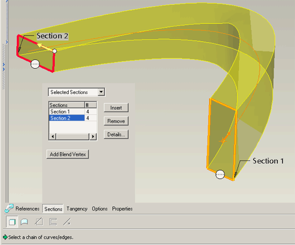
Under the section options change to Selected Sections. Pick your first sketch, then pick Insert to add to the list and then pick the next sketch along the trajectory. Continue to pick Insert and select the relevant sketch for all your sections.
If the previewed solid is twisted because the start points are not aligned, simply drag the start point marker to the appropriate vertex.

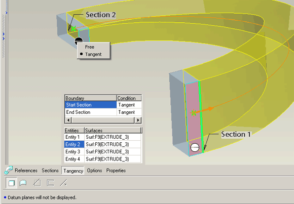
Tangent end conditions
If the feature is joined to a suitable geometry you can use the end condition markers to set tangency. In the below example some simple control surfaces were created prior to the sweptblend feature to enable setting tangency.

