Procedure Summary
Machining Considerations
Preparation
Tooling
Mill Geometry
Setting up a machining process
Volume Mill
Local Mill
Trajectory Milling
Holemaking
Engraving
Process Manager
Tool Movement Simulation
Post Processing
CNC Procedure Sheet
CNC Machining Tool Parameters
3d Machining
Unimatic Router
ProPlastic Advisor
3d Machining
In this section we will consider strategies and setting for machining complex 3D or non horizontal [XYplane] surfaces using the 3 axis CNC machines. Two fundamental issues to understand and overcome are surface finish and the minimum curvature on the machined surfaces.
Surface finish - Scallop height and ballnose cutters


Surface accuracy - Smoothness or Roughness
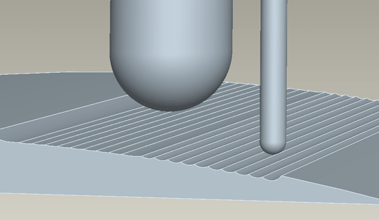
We cannot use a flat bottomed cutter to machine a non planer surface, therefore all your machining must be done with ballnosed cutters. A ballnosed cutter will machine its profile through the material producing a groove across the surface which has a radius equal to that of the cutter.
Therefore the combination of the cutter diameter and the stepover will dictate the surface finish. In the image above both the 20mm and the 4mm ballnose cutters are machining with a 1mm stepover. The smaller diameter will produce the coarser finish - using the largest available cutter will give allow the best surface finish and shortest cycle time. [Surface finish discussion here]
The deviation from the original surface [being followed by the tool tip] and the highest point of the groove is referred to as the cusp or scallop height.
The other important factor which controls the deviation from the reference surface is the number of coordinates output for toolpath.
Radii or Spline
CNC controllers will move two axis simultaneously to produce a planar radii. The code will specify the start and the end coordinates and the radius (R) or arc centre (I and J).
Controllers cannot follow a spline exactly as it has a constantly changing radius. Instead the spline is split into facets, the software outputs XYZ points along the spline. The number of points the spline is broken into is defined by accuracy setting in the CNC software which defines the chordal deviation from the reference surface. It is also defined by the curvature of the spline - a higher curvature will require more points to achieve the same chordal deviation.

1. Chord deviation 2. Reference surface 3. Chord
Click above image to enlarge
Cutter choice
The ballnose diameter we choose for as particular sequence is dictated by many things - availability, machine power, spindle capacity.
The most important factor is the minimum radius in the area you wish to machine
Suggested strategies and sequences
Volume mill by Window with 20mm flat bottomed
Surface Mill by Window initially with 20mm ball nosed cutter
Isolate smaller areas by window with smaller ball nosed cutters

