![]() Design & Tech CAD
Design & Tech CAD
Procedure Summary
Machining Considerations
Preparation
Tooling
Mill Geometry
Setting up a machining process
Volume Mill
Local Mill
Trajectory Milling
Holemaking
Engraving
Process Manager
Tool Movement Simulation
Post Processing
CNC Procedure Sheet
CNC Machining Tool Parameters
3d Machining
Unimatic Router
ProPlastic Advisor
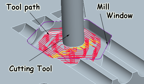
Mill Geometry
Definition: Geometry which limits the tool movements
Major use: Mill window - curve [sketch or edges] which defines x y boundary. Tool machines stock material inside boundary until it encounters reference model surfaces.
![]()
Mill Window
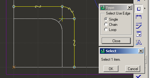
Method:
- Select a Window Plane (sketchplane)
- In the Dashboard, select the Sketch window type icon
- Select the front (not top) face of the block to face downward
- Select sketch references
- Sketch or copy edges to create window
Under Options the default is to limit your tool movement to inside the window, this can be changed to on or outside the window.
Mill Volume
Select surfaces or create a feature to represent a Mill Volume. Selecting surfaces is a long process, it is usually easier to use extrudes etc. or use a Mill Window.
You can create rounds on your Mill Volume. Once you have the volume feature completed, click on the Mill Volume Tool icon in the right toolbar and select the Round tool icon in the right toolbar. Select the edges in your mill volume.
Referencing existing edges
An underused tool which is essential when creating Mill Windows is the Use [copy] Edge tool in sketcher. A mill window needs to be robustly referenced to the edges in the reference model - if your reference model changes, the mill geometry will change.
The cutter may also follow a curve in a Trajectory sequence, in this case the curve is selected within the sequence.