Procedure Summary
Machining Considerations
Preparation
Tooling
Mill Geometry
Setting up a machining process
Volume Mill
Local Mill
Trajectory Milling
Holemaking
Engraving
Process Manager
Tool Movement Simulation
Post Processing
CNC Procedure Sheet
CNC Machining Tool Parameters
3d Machining
Unimatic Router
ProPlastic Advisor
Setting up a
machining process
Before you start any sequence make sure you understand what you are
proposing in practical terms, visualise going through the motions in a
practical session in the machine shop. This will tell you all the
information needed to make the sequence successful.
We shall primarily be using:
-
 Volume
Roughing [by window]
 -
 Previous Step - Local ['rest'] Mill
 -
 Trajectory Milling
 -
 Engraving
 -
 Holemaking
You can also use surface milling but this will not be supported in the Des. Manuf. module - see the 3D Machining section.
As you build the NC sequence you assign three main elements:
1. Tool
2. Parameters
3. Geometry
All of these elements can be redefined.
To start a Sequence
Choose the appropriate icon in the top toolbar.
You need to ensure that at least Tool and Parameters are ticked in the SEQ SETUP menu.
The geometry will be specified by different methods dependent of which sequence type you are constructing, ie. for an initial Volume Roughing you should choose Window in the SEQ SETUP menu to define the geometry to be machined.
To Modify a Sequence
Simply RMB > Edit Definition in the model tree as you would a model feature.
Tick the element you wish to modify and click Done
Tools
See the Tooling
section for setting up a tool for your sequence
Parameters

We are looking for the most efficient sequence types, sequence order and setting within the sequence which will minimise the machining time and maximise surface quality.

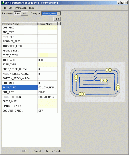
The figures and options set in the Parameters Window control how the machine executes the chosen sequence – spindle speed, cutter feed rate, step depth, the order that elements are machined, etc. Options highlighted yellow are minimum requirements for the sequence to function.
Ensure that all tools feed more slowly vertically [plunge] into materials than horizontally through material.
These Parameters will have to be ‘fine tuned’ to achieve the desired effect within the machining sequence. The Parameters Window can only be entered whilst setting up or modifying a sequence and the parameters are particular to that sequence.
It has two levels –
Basic and All – showing more or less parameters. You
can also view parameters by category.
Use the Manufacturing Parameters Tree
![]() icon in the top toolbar to enter the parameters window whilst
building a sequence.
icon in the top toolbar to enter the parameters window whilst
building a sequence.
Geometry
All sequences need to know where in the cavity geometry it is going to be applied. This definition will be different according to the sequence type, ie. a hole will simple need a coordinate (defined by an axis, point or cylindrical surface) but a trajectory mill will need a chain of edges or curves.
Geometry selection will be dealt with within each sequence description.
