![]() Design & Tech CAD
Design & Tech CAD
Procedure Summary
Machining Considerations
Preparation
Tooling
Mill Geometry
Setting up a machining process
Volume Mill
Local Mill
Trajectory Milling
Holemaking
Engraving
Process Manager
Tool Movement Simulation
Post Processing
CNC Procedure Sheet
CNC Machining Tool Parameters
3d Machining
Unimatic Router
ProPlastic Advisor
CNC Machining Tool Parameters
Parameters for Slot Drills on aluminium
|
Tool Dia. |
Spindle speed |
Horizontal |
Plunge |
Step depth |
Maximum [total] depth of cut |
|
2.5 |
6000 |
100 |
60 |
1 |
2.5 |
|
3 |
6000 |
200 |
60 |
1 |
6 |
|
6 |
5000 |
250 |
60 |
1 |
12 |
|
8 |
4000 |
300 |
60 |
1 |
14 |
|
10 |
3000 |
300 |
60 |
1 |
16 |
|
|
|
|
|
|
|
|
5.8 drill |
2500 |
- |
60 |
- |
10 |
|
|
|
|
|
|
|
|
0.5mm
Engraving |
6000 |
200 |
100 |
0.2 |
0.2 |
Remember to set a plunge feed rate – found in the Advanced area of the parameter window – all tools must feed more slowly into materials than horizontally through material.
Diameters between those stated are also available in 1mm increments.
All feed rates are in mm per minute.
Ball Nosed cutters - decrease feedrates by 20%
Tools above 10mm dia. can be used but are restricted by machine power and the clamping system used - seek appropriate advice.
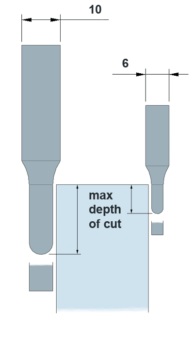
Maximum Depth of Cut
Whether it's a slot drill or ball nosed cutter, our standard tool range has either a 6mm or 10mm shank diameter. The cutter diameter will be equal to or less than this dimension - see below image. The maximum depth of cut is restricted by the length of the cutting edge, therefore if you want a 1.5mm radius in the corner of a pocket, that pocket can be no greater than 6mm deep – the cutting edge length of a 3mm dia. tool.
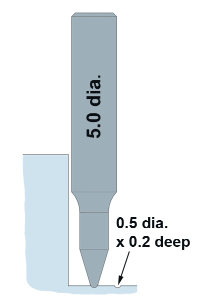
Engraving Tool
This tool will produce a line on a surface 0.5mm wide with a depth of cut of 0.2mm. This will show as a raised line on your widget and can be used for lettering and logos. Use with a Trajectory Mill sequence. Watch out for clearance from side walls in cavities - see below.
Tool Spindle Speeds and Feedrates
Surface Speed
A particular cutting tool material has an optimum speed at which it should travel through a particular material.
Example: The tip of a High Speed
Steel [HSS] cutting tool should
travel through aluminium at 150m/min.
Therefore we need to control the tip speed of the milling cutter at the radius of the tool - its circumference [in metres] multiplied by its revolutions per minute.
Spindle Speed
Spindle Speed = Surface Speed / Circumference
For a 10mm [0.01m] dia. cutter:
circum. = Pi x Dia = 3.14 x 0.01 = .0314m
For a cutting speed of 150m/min: 150m/.0314m = 4777rpm
|
Free cutting mild steel |
38 m/min |
|
Low carbon steel |
32 m/min |
|
Brass or bronze |
55 m/min |
|
Aluminium Alloys |
150 m/min |
|
Plastics |
250 m/min |
|
Woods |
500 m/min |
Feedrate
Feed rate is the distance a cutting tool moves
through the
material per minute.
This rate dictates how much material each tooth of the cutting tool removes per revolution.
Feedrate is dependent on the:
- Surface finish desired
- Power available at the spindle (to prevent stalling of the cutter or workpiece)
- Rigidity of the machine and tooling setup (ability to withstand vibration or chatter)
- Strength of the workpiece (high feed rates will collapse thin wall tubing)
- Characteristics of the material being cut, chip flow depends on material type and feed rate
- The ideal chip shape is small and breaks free early, carrying heat away from the tool and work.
Feed rate (mm/min) = Tooth Load (mm). X Number of teeth. X Spindle Speed in RPM.
Denford:
http://www.denford.com/Feeds and Speeds.html
Wiki: http://en.wikipedia.org/wiki/Cutting_speed