Procedure Summary
Machining Considerations
Preparation
Tooling
Mill Geometry
Setting up a machining process
Volume Mill
Local Mill
Trajectory Milling
Holemaking
Engraving
Process Manager
Tool Movement Simulation
Post Processing
CNC Procedure Sheet
CNC Machining Tool Parameters
3d Machining
Unimatic Router
ProPlastic Advisor
This sequence will remove a volume of material defined by the reference model. A Mill Window is the simplest method for defining the part of the reference model to be machined.
From the SEQ SETUP menu, ensure the minimum setup requirements are checked;
- tool
- parameters
- window
Click Done.
Select or set up the cutting tool, click OK.
Set the required parameters through the parameters window – this window has a Basic (the basic parameters) or All (all parameters) condition. (specialised parameters are discussed at the end of this section).
The next step is to select the window - see Mill Geometry section.
Once you have selected the window you will be returned to the NC Sequence menu.
Choose Play Path to simulate the sequence.
Choose Seq Setup to redefine any elements of the sequence.
** The Sequence is not complete until you select Done Seq **
Parameters
In the parameters windows, you must set:
CUT_FEED
PLUNGE_FEED
STEP_DEPTH
STEP_OVER
CLEAR_DIST
SPINDLE_SPEED
Other preferred options for a volume mill are:
SCAN_TYPE FOLLOW_HARDWALLS
ROUGH_OPTION ROUGH_ONLY
RETRACT_OPTION SMART
ROUGH_OPTION settings
Controls whether a profiling pass occurs during a Volume milling NC sequence, this will machine the perimeter of the volume. The options are:
ROUGH_ONLY Creates an NC sequence with no
profiling.
ROUGH_&_PROF Creates an NC sequence that rough cuts the milling volume,
then profiles the volume perimeter.
PROF_ONLY Only profiling is done.
Using PROF_ONLY could allow us to avoid a
trajectory mill sequence if we use it in a new sequence with a different
tool to finish the perimeter of a previously machined volume.
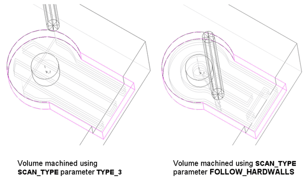
SCAN_TYPE settings
Controls how the tool moves in the cavity at each slice depth and how it deals with islands or holes in the cavity. The options are:
TYPE_1 The tool continuously machines the
volume, retracts upon encountering islands.
TYPE_2 The tool continuously machines the volume without retract, moving
around the islands upon encountering them.
TYPE_3 The tool removes material from continuous zones defined by the
island geometry, machining them in turn and moving around the islands.
Upon completing one zone, the tool may retract to mill the remaining
zones.
FOLLOW_HARDWALLS The tool will follow a path which is approximately
concentric with the perimeter of the cavity.
TYPE_3 and FOLLOW_HARDWALLS are generally the most efficient options for this sequence.
You will have to experiment with different parameter combinations and selection options to obtain your desired effect – remember it is very easy to redefine the sequence through the menu manager or through the parameters window (see Modification of NC Sequences on page 6).

Unlike a Slot Drill, a 4 fluted cutter cannot plunge vertically into a volume to a slice depth as it does not have a cutting edge across its axis. A Helical motion means it is cutting on its side as it plunges.
Parameters
RAMP_ANGLE [try approx 5 deg]
HELICAL_DIAMETER
