Procedure Summary
Machining Considerations
Preparation
Tooling
Mill Geometry
Setting up a machining process
Volume Mill
Local Mill
Trajectory Milling
Holemaking
Engraving
Process Manager
Tool Movement Simulation
Post Processing
CNC Procedure Sheet
CNC Machining Tool Parameters
3d Machining
Unimatic Router
ProPlastic Advisor
DP4 Machining Considerations
Because of time limitations in the
DMT
module, we have restricted
machining geometry to 2˝D Machining.
2˝D Machining refers to the action of removing material in z slices with the tool moving through 2D x,y coordinates. Therefore the tool feeds vertically down into the material to a specified depth and the then moves horizontally around that x,y plane removing material, it then feeds to the next z increment vertically down and removing another layer of material.
Machining complex 3D surfaces or non horizontal planar surfaces to an adequate surface finish requires a very small stepover [to minimise scallop height] with a ball nosed cutter - this will result in a long machining cycle, maybe 2 or 3 hours for a relatively small surface. There are also more complex considerations for merging into neighbouring surfaces which can take a lot of time to solve.

Above: scallops produced with ball nosed cutter on 3D surface
So, as you are considering your design and procedure sheet remember that the main restrictions are that you cannot machine any sloped or curved 3D surfaces and that you are limited in the shape and size of tools available. This is particularly important when considering z depths – a good ‘rule of thumb’ is that a tool may start to flex if it is greater than 1˝ times its diameter in length.
Split your tool into elements
To complete your procedure sheet you need to consider how each element of your mould can be best machined in terms of the tool type and size and the path it will take when removing material.
It doesn’t matter what geometry you’ve constructed in your reference model, the tool type and size and the path it takes will ultimately decide how the cavity will look.

Example: The reference model above left contains a rectangular cavity. If this was finish machined with a ball nosed cutter the result would be the cavity in the block on the right – you cannot machine the vertical square corners with a cutter in the standard orientation on the z axis.

There are two further issues with the resulting cavity (diagram above);
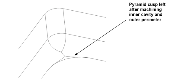
• firstly, it would have to be machined in two stages as the flat area in the bottom could not be produced with the balled nosed cutter – this would leave grooves [scallops] across the bottom of the cavity. A cavity which is smaller in x and y by the corner radius all round would have to be machined with a flat bottomed cutter.
• secondly, if we consider the previous image, there would be a small amount of material where the cutter used for the inner cavity would not be able to blend completely with the surface produced by the ball nosed cutter used to machine the perimeter. This material can be removed with some careful consideration.
