Procedure Summary
Machining Considerations
Preparation
Tooling
Mill Geometry
Setting up a machining process
Volume Mill
Local Mill
Trajectory Milling
Holemaking
Engraving
Process Manager
Tool Movement Simulation
Post Processing
CNC Procedure Sheet
CNC Machining Tool Parameters
3d Machining
Unimatic Router
ProPlastic Advisor
Post Processing
Once you have completed all the sequences required for your machining process they need to be interpreted into NC machine code for the specific machine you intend using, this process is referred to as Post Processing.
The process will generate a simple text file with the extension .tap which you will find in the working directory. The .tap extension may have to be changed according the machine you are going to use.
Through the drop down menus:
Edit > CL Data > Output
Operation> [select your operation name]
File> [tick the MCD File checkbox] >Done
An .ncl file needs to be generated, give it an appropriate name say, your user ID – this will be the name of your .tap file - and click Done
Leave the defaults in the PP OPTIONS menu and click Done
The PP LIST then offers you a number of Post Processor files;
UNCX01.P01 Denford Mill
UNCX01.P02 Denford Mill - no arcs
UNCX01.P03 Denford Mill - Easimill/Heidenhain
UNCX01.P04 Denford Router - no arcs
UNCX01.P05 Denford Router - with arcs
UNCX01.P06 Boxford A3HSR Router
UNCX01.P07 Boxford 500HSR Router
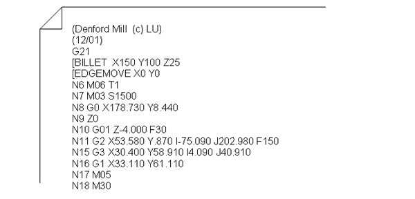
This file can be viewed with a standard text editor. Some outputs will require a small amount of manual editing before submitting to the machine. The file consists of x,y,z tool movement coordinates, and control codes.

M codes are machine control codes;
M06 is a tool change, followed by the tool number T.
M03 starts the spindle at the appropriate spindle speed S.
M05 stops the spindle.
G codes are movement control codes;
G0 is a rapid positioning movement whilst not cutting.
G1 is a linear movement at a feed rate F.
G2 and G3 are clockwise and counter clockwise arc movements.
G80, 81 and 83 are drilling cycle codes.
